Machine vision basics
Machine vision 101: guidance, inspection, gauging and identification
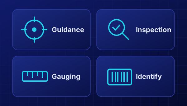
What machine vision actually does on a production line, explained through its four core jobs: guidance, inspection, gauging and identification.
Machine vision is the use of cameras, lighting, optics and software to make automatic decisions about parts on a production line. Where a human inspector gets tired, distracted or inconsistent over a long shift, a vision system checks every part the same way, at line speed, and keeps a record of what it saw.
That sounds broad, and it is. But almost every industrial vision application comes down to one or more of four jobs. Understanding them is the fastest way to work out what a vision system can do for your line.
The building blocks of a vision system
Before looking at the four jobs, it helps to know what's inside a typical system:
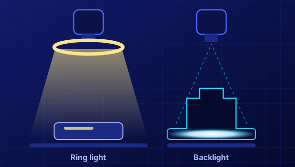
- Lighting makes the feature you care about stand out from everything else. It's the most underestimated part of any system (we've written a whole guide to it).
- Optics (the lens) sets the field of view, working distance and how much detail reaches the sensor.
- The camera turns light into an image. Resolution, sensor size and speed are chosen to suit the part and the cycle time.
- Software analyses the image: finding the part, measuring it, checking it or reading it.
- Integration connects the result to the real world: triggering, reject mechanisms, robot communication and data logging.
1. Guidance: where is the part?
Guidance systems locate a part and report its position and orientation, usually as X, Y and angle, to a robot, pick-and-place head or motion system. This lets automation handle parts that arrive in slightly different positions instead of relying on precise, expensive fixtures.
Typical guidance applications include robot pick-and-place from trays or conveyors, alignment before assembly, and counting or sorting parts. The key to good guidance is calibration: the vision system's pixel coordinates have to be accurately mapped to the robot's coordinate system, and that mapping has to stay stable.
2. Inspection: is the part good?
Inspection is what most people picture when they hear "machine vision": checking every part for defects and rejecting the bad ones. Common inspections look for:
- Surface defects such as scratches, cracks, nicks, voids and contamination
- Missing or extra features, like a missing pin, hole or component
- Shape problems such as flash, short shots or deformation on moulded parts
- Colour and print quality
The hardest part of an inspection project is usually not the software. It's agreeing on what counts as a defect. A clear defect specification, with real good and bad sample parts, is the single most useful thing you can bring to a vision project.
3. Gauging: is it the right size?
Gauging systems measure dimensions from the image and compare them with your tolerances: lengths, diameters, gaps, pitch, angles and positions. Because nothing touches the part, you can measure 100% of production instead of pulling samples to a lab.
Measurement accuracy depends on the whole system, not just the camera. A common rule of thumb is that measurement resolution should be around one tenth of the tolerance band. Sub-pixel edge detection helps, but the field of view, lens quality and lighting still set the limits. For precise gauging, a backlight and a telecentric lens (which removes perspective error) are often the right combination.
4. Identification: which part is it?
Identification systems read the codes and text on parts and labels so every unit can be traced through production:
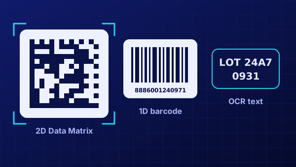
- 1D barcodes for simple IDs on labels and packaging
- 2D codes such as Data Matrix, which store more data in less space and can be marked directly onto parts
- OCR and OCV, which read or verify human-readable text like serial numbers and lot codes
Choosing between them depends on how much data you need, how much space you have and how the mark is made. Our article on barcodes, 2D codes and OCR covers the trade-offs in detail.
Most real applications combine all four
In practice, the four jobs are rarely separate. Take a connector production line: the system first locates the connector, then measures pin pitch and position, inspects the housing for cracks and flash, and finally reads the 2D code for traceability, all from one or two images in a fraction of a second.
That's why it pays to think about the whole process rather than a single check. A system designed around all of your requirements from the start is simpler, faster and cheaper than several bolted together later.
Where to start
If you're considering machine vision for your line, these questions will make the first conversation much more productive:
- What is the part, and what are you trying to find, measure or read?
- Do you have good and bad sample parts, or photos of real defects?
- How fast is the line, and how is the part presented to the camera?
- What should happen when a part fails: reject, stop, alarm or log?
- Do you need to store results or images for traceability?
You don't need all the answers up front. That's what a vision consultation is for. But thinking them through will help you get to the right solution faster. When you're ready, get in touch and tell us what you're working on.